We define apparent power as the product of Vrms magnitude and Irms magnitude. Since the voltage might be leading or lagging the current, there might be a phase difference between them. We represent the phase difference by using the power factor.
Since voltage and current have a real part and a imaginary part. We define complex power as the combination of both. The apparent power can be considered as the magnitude of the complex power, and the power factor is the cosine value of the angle. In rectangular format, the real term is called the real power, the imaginary term is called the reactive power.
Then we did a lab to test the new definitions of power. Here is a schematic of the circuit.
We applied different resistance values to the load resistor and measured them in the oscilloscope.
10Ω
47Ω
100Ω
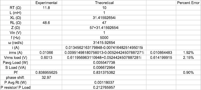
Then we compared the experimental values with theoretical values
10Ω
47Ω
100Ω
Summary: We concluded a list of useful formulas regarding power in AC circuits.
RMS Value of a Sinusoid
Vrms =Vp /√2
Irms =Ip /√2
Impedance
Z = R + j X = |Z|∠θ
|Z| = (R2 + X2)1/2
θ = tan−1(X/R)
Note: θ is the angle of the load impedance (We have suppressed the subscript z.)
Ohm’s Law in Frequency Domain V = IZ
Vp = Ip |Z|
Vrms = V / √ 2
Irms =I/√2
Vrms = Irms |Z|
θv −θi =θ
θ > 0 when X > 0 (Inductive impedance) θ < 0 when X < 0 (Capacitive impedance)
Average Power (W)
P = Vrms Irms cosθ = Irms2 R = (Vrms2 cosθ)/|Z|
Power Factor
pf=cosθ=R/(R2 +X2)1/2, 1≥pf≥0.
If θ > 0 (inductive impedance), θi < θv, pf lagging
If θ < 0 (capacitive impedance), θi > θv, pf leading
If θ = 0 for purely resistive load and the pf is unity
Reactive Power (VAR) Q = Vrms Irms sinθ = Irms2 X
Apparent Power (VA) S=Vrms Irms =Irms2 |Z|=Vrms2 /|Z|
Complex Power (VA)
S=Vrms (Irms)*=Vrms Irms ∠θ=P+jQ=Irms2 Z=(Vrms)2/Z*


