Saturday, June 10, 2017

Final Project Color Organ Alex & Tony

Our final project is "Color Organ". This circuit uses inexpensive parts and cases. The components we used can be easily obtained, but it still has super cool visual effects.

We made a PERT chart at first.


A schematic of our circuit is as following:

There are three transistor filters on the schematic. The right one is a low-pass filter. It turns on when the frequency is below the cutoff frequency. The middle one is a band-pass filter. It turns on when the frequency is between the two cutoff frequencies. The left one is a high-pass filter. It turns on when the frequency is above the cutoff frequency. The two audio inputs represent the left channel and the right channel.


We made a list of all the parts included in the circuit design
  • 3x 100 ohm resistors
  • 1x 180 ohm resistors
  • 1x 270 ohm resistors
  • 2x 1k ohm resistors
  • 4x 2.2k ohm resistors
  • 2x 10k ohm resistors
  • 1x 0.047 uF capacitor
  • 1x 0.01 uF capacitor
  • 1x 0.47 uF capacitor
  • 1x 1 uF capacitor
  • 1x 10 uF capacitor
  • 1x 1N4148 diode
  • 1x 2N2222A, 2N3904 or equivalent NPN transistor
  • 3x 2N2907A, 2N3906 or equivalent PNP transistor
  • 6x LED (2x Red, 2x Green, 2x Blue recommended)
After we checked the parts available in the classroom, the huge list shrinks to a small one consisting of a few items
  • 1x 180Ω resistor
  • 1x 270Ω resistor
  • 1x 0.047 uF capacitor
  • 1x 0.01 uF capacitor
  • 1x 1N4148 diode
We bought all the parts on Tayda and constructed the first version of the circuit.


It turns out the components are too crowded on the board. We also made a few modifications to it to get our second version.


The three wires at the bottom left corner are the audio inputs. We used an old audio jack extension cord and cut off the male port. The three wires are left channel, right channel and ground (yellow wire).

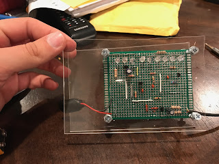
The second version turned out to be working, so we moved the whole circuit to a solder board.
We added one LED for each color. That is the only adjustment we made in this version.

Then we added a case for the circuit to survive a drop test.

Here is a video of it working.

Passive RL Filter

Today we continued resonance circuits. Last time we went over series resonance circuits. This time we did parallel resonance circuits. It turns out they have the same formula for resonance frequency. Here is a table of the formulas
Then we went over passive filters. There are four types of passive filters. They are lowpass, highpass, bandpass and bandstop

Here are the transfer functions of different passive filters
Lowpass
Highpass
Bandpass

Then we did a lab on passive RL filter. We found the resonance frequency to be 100000 rad/s. We applied different frequencies on the AC voltage input.

ωc/10


ωc/8

ωc/4

ωc/2

ωc

2ωc

4ωc

8ωc

10ωc

Summary: For RL passive filters. If the voltage across the inductor is taken as the filter output, the circuit will act as a high-pass filter. However, if we take the voltage across the resistor as the filter output, the circuit acts as a low-pass filter. The higher the frequency is, the more voltage will be allocated to the inductor and the less voltage will be allocated to the resistor. The lower the frequency is, the more voltage will be allocated to the resistor and the less voltage will be allocated to the inductor. Also, when the frequency is higher, the phase shift of the resistor is higher and the phase shift of the inductor is lower. When the frequency is lower, the phase shift of the resistor is lower and the phase shift of the inductor is higher.
 

Thursday, June 8, 2017

Bode Plots (No Lab)

Today we introduced Bode plots. Bode plots are semilog plots of the magnitude (in decibels) and phase (in degrees) of a transfer function versus frequency.

The magnitude is in a logarithmic scale. HdB =20log10 H
Any transfer function can be represented as following: 
There are four different factors:
1. A gain K
2. A pole (jω)1 or zero (jω) at the origin
3. A simple pole 1/(1 + jω/p
1 ) or zero (1 + jω/z 1 )
4. A quadratic pole 1/*1 + j2ζ 2 ω/ω n + (jω/ω n )2 + or zero *1 + j2ζ 1 ω/ω k + (jω/ω k )2 ]

An approximation of the magnitude is a linear part and a constant part. An approximation of the phase is a linear function whose slope is 45º per decade.  

Then we went over the concept of resonance. Resonance is a condition in an RLC circuit in which the capacitive and inductive reactances are equal in magnitude, thereby resulting in a pure resistive impedance. the load has maximum power at resonance frequency ω0. there is a half-power frequency on either side of the resonance frequency. the distance between them is called bandwidth B. Quality factor Q is defined as ω0/B. The quality factor represents the sharpness of the frequency response. 
For RLC in series
Summary: 


Sunday, June 4, 2017

Signals with Multiple Frequency Components

Today we went over transfer functions. The transfer function H is the frequency-dependent ratio of a phasor output to a phasor input. There are four possible transfer functions.
1. Voltage Gain Vout/Vin
2. Current Gain Iout/Iin
3. Transfer Impedance Vout/Iin
4. Transfer Admittance Iout/Vin
A zero is defined as a root of the numerator. A pole is defined as a root of the denominator.

We also went over the decibel scale
GdB = 10log10(P2/P1) = 20log10(V2/V1)-10log10(R2/R1)
Then we did a lab on the frequency response.

We applied different resistance to the circuit.
500Ω

1000Ω

10kΩ

Summary: When ω = 0, the gain is 0.5. When ω = , the gain is 0. When ω increases, the gain decreases. When ω decreases, the gain increases.

Monday, May 29, 2017

Apparent Power and Power Factor

Today we went over all kinds of definitions of power regrading AC circuits. Unlike DC circuit, AC circuit has different values of voltage and current at different moments. Using the original definition for DC circuits on AC circuits only shows the instantaneous power. It does not tell us enough information about the circuit. Then we introduced the idea of effective voltage and current, which is equal to Vrms and Irms respectively.

We define apparent power as the product of Vrms magnitude and Irms magnitude. Since the voltage might be leading or lagging the current, there might be a phase difference between them. We represent the phase difference by using the power factor.

Since voltage and current have a real part and a imaginary part. We define complex power as the combination of both. The apparent power can be considered as the magnitude of the complex power, and the power factor is the cosine value of the angle. In rectangular format, the real term is called the real power, the imaginary term is called the reactive power.


Then we did a lab to test the new definitions of power. Here is a schematic of the circuit.

We applied different resistance values to the load resistor and measured them in the oscilloscope.

10Ω

47Ω

100Ω
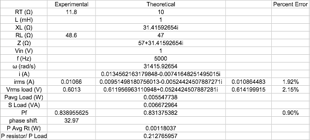
Then we compared the experimental values with theoretical values

10Ω

47Ω

100Ω

Summary: We concluded a list of useful formulas regarding power in AC circuits.

RMS Value of a Sinusoid
Vrms =Vp /
Irms =Ip /2

Impedance
Z = R + j X = |Z|∠θ
|Z| = (R2 + X2)1/2
θ = tan1(X/R)
Note: θ is the angle of the load impedance (We have suppressed the subscript z.)

Ohm’s Law in Frequency Domain V = IZ
Vp = Ip |Z|
Vrms = V / 2
Irms =I/2
Vrms = Irms |Z|
θv −θi =θ
θ
> 0 when X > 0 (Inductive impedance) θ < 0 when X < 0 (Capacitive impedance)

Average Power (W)
P = V
rms Irms cosθ = Irms2 R = (Vrms2 cosθ)/|Z|

Power Factor
pf=cos
θ=R/(R2 +X2)1/2, 1pf0.
If
θ > 0 (inductive impedance), θi < θv, pf lagging 
If θ < 0 (capacitive impedance), θi > θv, pf leading 
If θ = 0 for purely resistive load and the pf is unity

Reactive Power (VAR) Q = Vrms Irms sinθ = Irms2 X
Apparent Power (VA) S=Vrms Irms =Irms2 |Z|=Vrms2 /|Z|
Complex Power (VA)
S=Vrms (Irms)*=Vrms Irms ∠θ=P+jQ=Irms2 Z=(Vrms)2/Z

Thursday, May 25, 2017

Op Amp Relaxation Oscillator

Today we are introduced to a new circuit device called oscillator. An oscillator is a circuit that produces an AC waveform as output when powered by a DC input. In order to make an oscillator, the Barkhausen criteria have to be met. The overall gain must be unity or greater. Therefore, loss has to be compensated for by an amplifying device. The overall phase shift has to be zero.

The Wien-bridge oscillator is a common type of oscillator. It is an operational amplifier circuit with resistors and capacitors in it. It it limited to operating in the frequency range of 1MHz or less.

Then we did a lab to build a operational amplifying. Here is a schematic of the circuit

Here is the setup of the circuit

Summary: Oscillators can be used to convert DC signals to AC signals. It can be achieved by using operational amplifiers. The charge and discharge of capacitors of the circuit generate the alternating circuit signal.

Sunday, May 21, 2017

Sinusoidal Circuit Analysis (No Lab)

Today we went over the circuit analysis methods that we used to solve DC circuits. Here is a list of all the methods.

The above methods still work in AC circuits as they work in DC circuits. Here are some examples of what we did in class.

Nodal Analysis

Mesh Analysis

Superposition

Source Transformation

Summary: Notice that superposition method is the only one that works for sources of different frequencies. When we turn off and on a different source, the impedances of capacitors and inductors have to be recalculated since they are frequency-dependent. All the other methods still work in AC circuits as long as frequency stays constant.

Impedance

Today we derived the impedance of resistor, capacitor and inductor. The impedance of a resistor is R; the impedance of a capacitor is -j/ωC or 1/jωC; the impedance of an inductor is jωL. It is obvious that the impedance of a capacitor or an inductor changes when different frequency is applied.

Impedance can be expressed as Z = R + Xj. Z is called impedance. R is called resistance. X is called reactance.

We also have the definition of their reciprocals. Y = G + Bj. Y is called admittance. G is called conductance. B is called susceptance.

Then we did a lab on impedance. We applied different frequencies to different types of circuit elements.

Resistor

R (Ω)47
R0 (Ω)100
Z (Ω)147
f (kHz)1
ω (rad/s)6283.185307
Vin (V)2
i (A)0.01360544218
Vout (V)1.360544218
Gain0.6802721088
Phase Difference (º)0

Capacitor 1kHz
R (Ω)47
C (μF)0.1
XC (Ω)1591.549431-90
Z (Ω)1592.243258-88.30849159
f (kHz)1
ω (rad/s)6283.185307
Vin (V)20
i (A)0.00125608947788.30849159
Vout (V)1.999128492-1.691508405
Gain0.9995642459
Phase Difference (º)-1.691508405

Capacitor 5kHz
R (Ω)47
C (μF)0.1
XC (Ω)318.3098862-90
Z (Ω)321.7610661-81.60068958
f (kHz)5
ω (rad/s)31415.92654
Vin (V)20
i (A)0.00621579243481.60068958
Vout (V)1.978548182-8.399310418
Gain0.9892740911
Phase Difference (º)-8.399310418
Capacitor 10kHz
R (Ω)47
C (μF)0.1
XC (Ω)159.1549431-90
Z (Ω)165.9496789-73.54761774
f (kHz)10
ω (rad/s)62831.85307
Vin (V)20
i (A)0.0120518461673.54761774
Vout (V)1.91811089-16.45238226
Gain0.959055445
Phase Difference (º)-16.45238226
Inductor 1kHz
R (Ω)47
L (mH)1
XL (Ω)6.28318530790
Z (Ω)47.41812337.614427915
f (kHz)1
ω (rad/s)6283.185307
Vin (V)20
i (A)0.04217796616-7.614427915
Vout (V)0.265011977382.38557208
Gain0.1325059886
Phase Difference (º)82.38557208
Inductor 5kHz
R (Ω)47
L (mH)1
XL (Ω)31.4159265490
Z (Ω)56.5328262233.75971669
f (kHz)5
ω (rad/s)31415.92654
Vin (V)20
i (A)0.03537767584-33.75971669
Vout (V)1.11142246556.24028331
Gain0.5557112325
Phase Difference (º)56.24028331
Inductor 10kHz
R (Ω)47
L (mH)1
XL (Ω)62.8318530790
Z (Ω)78.4655450553.20247414
f (kHz)10
ω (rad/s)62831.85307
Vin (V)20
i (A)0.0254888945-53.20247414
Vout (V)1.60151447436.79752586
Gain0.8007572372
Phase Difference (º)36.79752586
Summary: The impedance of resistors is independent from frequency. The magnitude of impedance of capacitors and inductors are related to the frequency. Larger frequency will cause the capacitor impedance to be smaller and the inductor impedance to be bigger. Smaller frequency will cause the capacitor impedance to be bigger and the inductor impedance to be smaller.