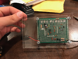
Our final project is "Color Organ". This circuit uses inexpensive parts and cases. The components we used can be easily obtained, but it still has super cool visual effects.
We made a PERT chart at first.
A schematic of our circuit is as following:
There are three transistor filters on the schematic. The right one is a low-pass filter. It turns on when the frequency is below the cutoff frequency. The middle one is a band-pass filter. It turns on when the frequency is between the two cutoff frequencies. The left one is a high-pass filter. It turns on when the frequency is above the cutoff frequency. The two audio inputs represent the left channel and the right channel.
We made a list of all the parts included in the circuit design
- 3x 100 ohm resistors
- 1x 180 ohm resistors
- 1x 270 ohm resistors
- 2x 1k ohm resistors
- 4x 2.2k ohm resistors
- 2x 10k ohm resistors
- 1x 0.047 uF capacitor
- 1x 0.01 uF capacitor
- 1x 0.47 uF capacitor
- 1x 1 uF capacitor
- 1x 10 uF capacitor
- 1x 1N4148 diode
- 1x 2N2222A, 2N3904 or equivalent NPN transistor
- 3x 2N2907A, 2N3906 or equivalent PNP transistor
- 6x LED (2x Red, 2x Green, 2x Blue recommended)
- 1x 180Ω resistor
- 1x 270Ω resistor
- 1x 0.047 uF capacitor
- 1x 0.01 uF capacitor
- 1x 1N4148 diode
We bought all the parts on Tayda and constructed the first version of the circuit.

It turns out the components are too crowded on the board. We also made a few modifications to it to get our second version.

The three wires at the bottom left corner are the audio inputs. We used an old audio jack extension cord and cut off the male port. The three wires are left channel, right channel and ground (yellow wire).
The second version turned out to be working, so we moved the whole circuit to a solder board.
We added one LED for each color. That is the only adjustment we made in this version.
Then we added a case for the circuit to survive a drop test.
Here is a video of it working.


No comments:
Post a Comment